Since the introduction of the Nvidia RTX graphics cards last summer, ray tracing is back again. In the last months, my Twitter feed flooded with a continuous stream of RTX On / RTX Off comparisons.
After seeing so many nice images, I wanted to get experience combining a classical forward renderer and a ray tracer.
Suffering from the not-invented-here syndrome, I created my own hybrid rendering engine using WebGL1. You can try this demo rendering a Wolfenstein 3D level with some spheres (because of ray tracing) here: https://renderqueue.dev/wolfenstein.
Prototype
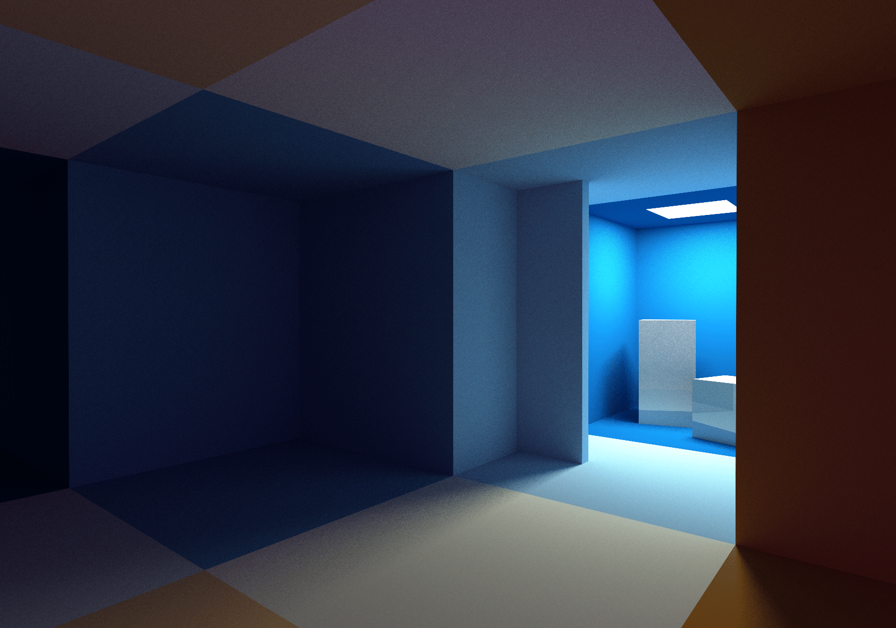
I started this project by creating a prototype to recreate the Ray Traced Global Illumination of Metro Exodus.
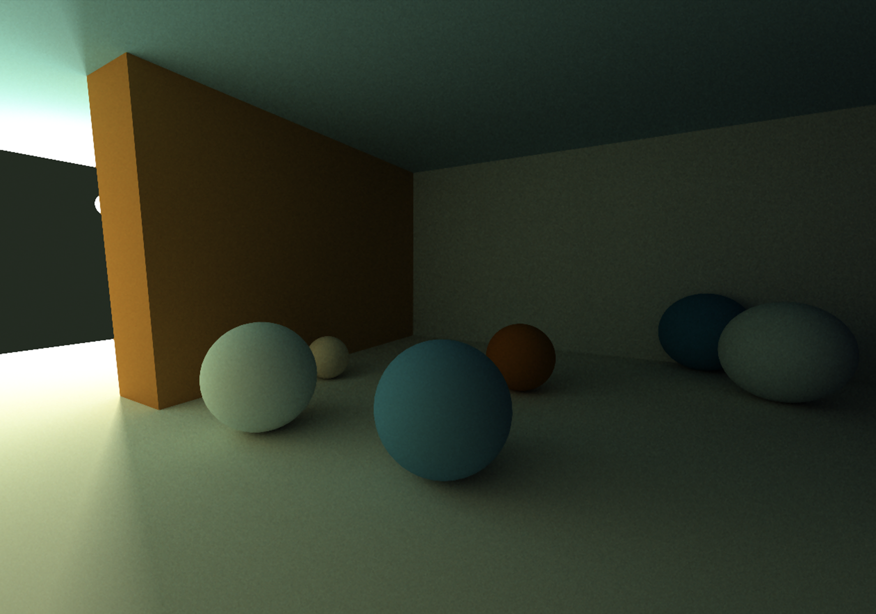
The prototype is based on a forward renderer that draws all the geometry in the scene. The shader used to rasterize the geometry calculates direct lighting and casts random rays from the surface of the rendered geometry to collect the indirect light reflection due to non-shiny surfaces (Diffuse GI) using a ray tracer.
In the image to the right, you can see how all spheres are correctly lit by indirect lighting only (the light rays bounce on a wall behind the camera). The brown wall on the left of the image occludes the light source.
Wolfenstein 3D
The prototype uses a very simple scene. There is only one light, and only a few spheres and cubes are rendered. This makes the ray tracing code in the shader straightforward. A brute force intersection loop where the ray is tested with all cubes and spheres in the scene is still fast enough to get a program that runs fine in real time.
After creating the prototype, I wanted to make it more complex by adding more geometry and many lights to the scene.
The problem with having a more complex environment is that I still had to be able to ray-trace the scene in real time. Normally a bounding volume hierarchy (BVH) would be used as an acceleration structure to speed up the ray trace process, but my decision to make this project in WebGL1 didn’t help here: in WebGL1 it is not possible to upload 16-bit data to a texture, and you cannot use binary operations in a shader. This makes it hard to pre-calculate and use BVH’s in WebGL1 shaders.
I decided to use a Wolfenstein 3D level for this demo. In 2013, I created a single WebGL fragment shader on Shadertoy that renders a Wolfenstein-like level and procedurally creates all textures needed. From this experience, I knew that the grid-based level design of Wolfenstein could also be used as a fast and simple acceleration structure and that ray tracing through this structure would be very fast.
You can play the demo in the iframe below or play it full-screen here: https://renderqueue.dev/wolfenstein.
Overview
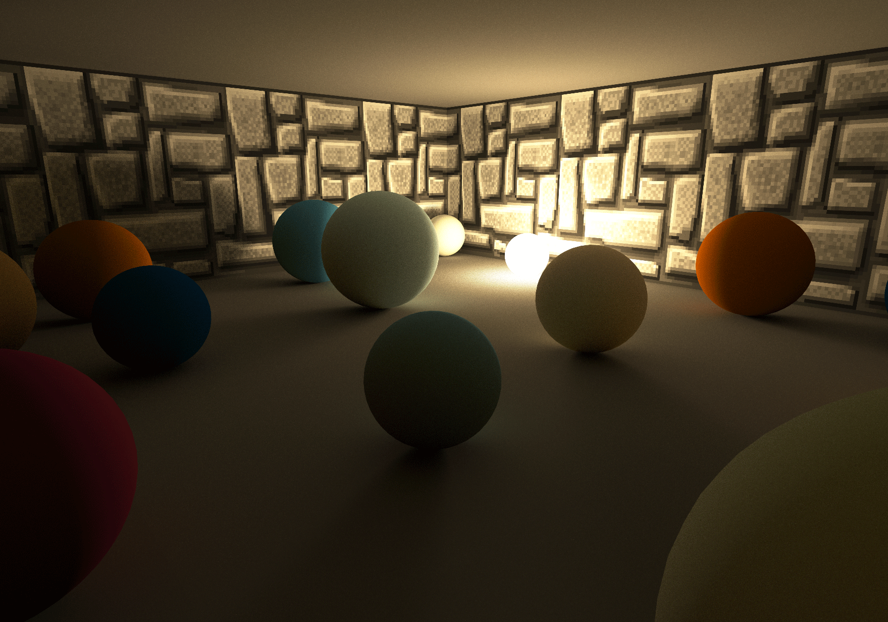
The demo uses a hybrid rendering engine. It uses traditional rasterization technologies to render all the polygons in a frame and then combines the result with ray traced shadows, diffuse GI and reflections.
Forward rendering
The maps in Wolfenstein can be fully encoded in a 2D 64×64 grid. The map used in the demo is based on the first level of episode 1 of Wolfenstein 3D.
At startup, all the geometry needed for the forward pass is created. Based on the map, a mesh for the walls is generated. A plane for the ground and ceiling is created, and separate meshes are created for the lights, doors, and randomly placed spheres.
All the textures used for the walls and doors are packed in a single texture atlas, so all walls can be drawn using a single draw call.
Shadows and lighting
Direct lighting is calculated in the shader used for the forward rendering pass. Each fragment can be lit by (at most) four different lights. To know which lights could affect a fragment in the shader, a look-up texture is pre-calculated at startup. This look-up texture is 64 by 128 and encodes the four nearest visible light positions for every position in the grid of the map.
varying vec3 vWorldPos;
varying vec3 vNormal;

void main(void) {
    vec3 ro = vWorldPos;
    vec3 normal = normalize(vNormal);
    vec3 light = vec3(0);

    for (int i=0; i<LIGHTS_ENCODED_IN_MAP; i++) {
        light += sampleLight(i, ro, normal);
    }Code language: GLSL (glsl)
To get soft shadows, for each fragment, for each light, a random position in the light is sampled. Using the ray trace code available in the shader (see below: Ray tracing), a shadow ray is cast to the sample point to determine the visibility of the light.
Eventually, after adding (optional) reflections (see below: Reflection), diffuse GI is added to the calculated fragment
Ray tracing
Whereas in the prototype, the ray trace code for the diffuse GI was combined with the forward shader, I decided to decouple both in the final demo.

The decoupling is done by drawing all geometry a second time to a separate render target (the Diffuse GI Render Target), using a different shader that only casts the random rays to collect the diffuse GI (see below: Diffuse GI). The collected light in this render target is added to the calculated direct lighting in the forward render pass.
By decoupling both the forward pass and the diffuse GI, it is possible to cast less than one diffuse GI ray per screen pixel. You can do this by decreasing the Buffer Scale (adjust the slider in the controls at the top right of the screen).
If, for example, the Buffer Scale is .5, only one ray for every four screen pixels will be cast. This gives a huge performance boost. Using the same UI in the top right of the screen, you can change the samples per pixel of the render target (SPP) and the number of bounces of the ray.
Cast a ray
To cast a ray through the scene, a representation of all geometry in the level is needed in a format that a ray tracer can use in a shader. A Wolfenstein level is encoded in a 64×64 grid, so it is pretty simple to encode all data in a single 64×64 texture:
- In the red channel of the texture, all objects at the corresponding x,y cell in the map’s grid are encoded. If the red channel is zero, no object exists in the cell; otherwise, a wall (values 1 to 64), a door, a light, or a sphere occupies the cell and should be tested for intersection.
- If a sphere occupies the cell in the grid of the level, the green, blue, and alpha channels are used to encode the radius and the sphere’s relative x and y position inside the grid cell.
Casting a ray through the scene is done by stepping through this texture using the following code:
bool worldHit(n vec3 ro,in vec3 rd,in float t_min, in float t_max,
              inout vec3 recPos, inout vec3 recNormal, inout vec3 recColor) {
    vec3 pos = floor(ro);
    vec3 ri = 1.0/rd;
    vec3 rs = sign(rd);
    vec3 dis = (pos-ro + 0.5 + rs*0.5) * ri;

    for( int i=0; i<MAXSTEPS; i++ )	{
        vec3 mm = step(dis.xyz, dis.zyx);
        dis += mm * rs * ri;
        pos += mm * rs;

        vec4 mapType = texture2D(_MapTexture, pos.xz * (1. / 64.));

	if (isWall(mapType)) {
            ...
            return true;
	}
    }
    return false;
}Code language: GLSL (glsl)
Similar ray trace code through a grid can be found in this Wolfenstein shader on Shadertoy.
After calculating the intersection point with a wall or a door (using a box intersection test), a lookup in the same texture atlas as used in the forward pass gives the albedo of the intersection point. The spheres have a color that is procedurally determined based on their x,y position in the grid and a color gradient function.
Doors are a bit problematic because they can move. To make sure that the scene representation on the CPU (used to render the meshes in the forward pass) is the same as the scene representation on the GPU (used for the ray tracing), all doors are moved automatically and deterministically based on the distance between the camera and the door.
Diffuse GI
The diffuse GI is calculated by casting rays in a shader to draw all geometry to the Diffuse GI Render Target. The direction of these rays is based on the normal of the surface using cosine weighted hemisphere sampling.
Given ray direction rd and starting point ro, bounced lighting is calculated using the following loop:
vec3 getBounceCol(in vec3 ro, in vec3 rd, in vec3 col) {
    vec3 emitted = vec3(0);
    vec3 recPos, recNormal, recColor;

    for (int i=0; i<MAX_RECURSION; i++) {
        if (worldHit(ro, rd, 0.001, 20., recPos, recNormal, recColor)) {
//            if (isLightHit) { // direct light sampling code
//                return  vec3(0);
//            }
            col *= recColor;
            for (int i=0; i<2; i++) {
                emitted += col * sampleLight(i, recPos, recNormal);
            }
        } else {
            return emitted;
        }
        rd = cosWeightedRandomHemisphereDirection(recNormal);
        ro = recPos;
    }
    return emitted;
}Code language: GLSL (glsl)
To reduce noise, direct light sampling is added to the loop. This is similar to the technique used in my shader Yet another Cornell Box on Shadertoy.
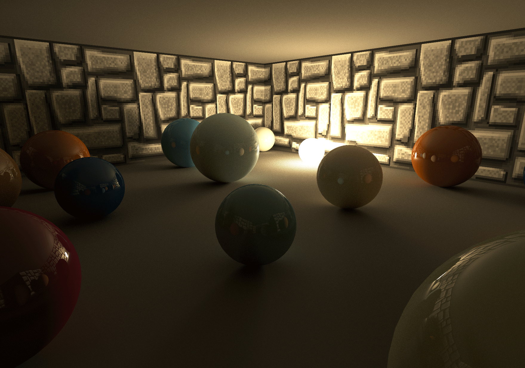
Reflection
Having the option to ray trace the scene in a shader makes it easy to add reflections. In this demo, reflections are added by calling the same getBounceCol method as displayed above, using the reflected camera ray:
#ifdef REFLECTION
    col = mix(col, getReflectionCol(ro, reflect(normalize(vWorldPos - _CamPos), normal), albedo), .15);
#endifCode language: GLSL (glsl)
Reflections are added in the forward rendering pass. Consequently, always one reflection ray per screen pixel will be cast.
Temporal anti-aliasing
As only ~1 sample per pixel is used for both the soft shadows in the forward rendering pass and the approximation of the diffuse GI, the result is extremely noisy. To reduce noise, temporal anti-aliasing (TAA) is implemented following Playdead’s TAA implementation: Temporal Reprojection Anti-Aliasing in INSIDE.
Reprojecting
The main idea behind TAA is quite simple: TAA computes a single subpixel per frame and then averages its value with the correlated pixel of the previous frame.
To know where the current pixel was located in the previous frame, the position of the fragment is reprojected using the model-view-projection matrix of the previous frame.
Sample rejection and neighbourhood clamping
In some cases, the history sample is invalid, for example, when the camera has moved in such a way that the fragment of the current frame was occluded in the previous frame. To reject those invalid samples, neighbourhood clamping is used. I ended up using the most simple type of clamping:
vec3 history = texture2D(_History, uvOld ).rgb;

for (float x = -1.; x <= 1.; x+=1.) {
    for (float y = -1.; y <= 1.; y+=1.) {
        vec3 n = texture2D(_New, vUV + vec2(x,y) / _Resolution).rgb;
        mx = max(n, mx);
        mn = min(n, mn);
    }
}

vec3 history_clamped = clamp(history, mn, mx);Code language: GLSL (glsl)
I also tried to use a bounding-box-based clamp method, but I didn’t see much difference with the current approach. This is probably because the scene in the demo has a lot of similar, dark colors, and there are almost no moving objects.
Camera Jitter
To get anti-aliasing, the camera jitters each frame using a (pseudo) random subpixel offset. This is done by modifying the projection matrix:
this._projectionMatrix[2 * 4 + 0] += (this.getHaltonSequence(frame % 51, 2) - .5) / renderWidth;
this._projectionMatrix[2 * 4 + 1] += (this.getHaltonSequence(frame % 41, 3) - .5) / renderHeight;Code language: JavaScript (javascript)
Noise
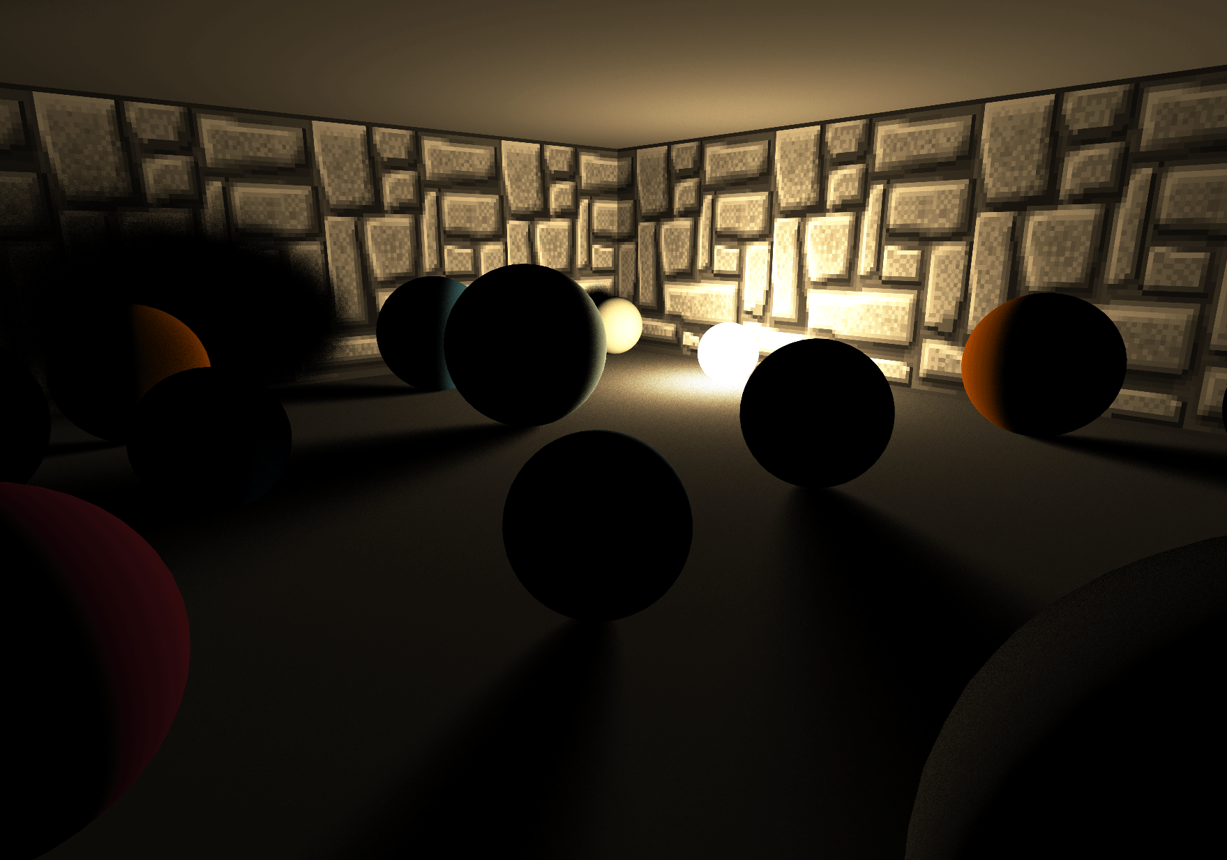
Noise is the basis of the algorithms used to calculate diffuse GI and soft shadows. Using good noise will greatly impact image quality, whereas using bad noise will give artefacts or slow converging images.
I’m afraid the white noise in this demo is not very good.
Using good noise is probably the most important thing to improve the image quality of this demo, for example, by using blue noise.
I did some experiments with golden-ratio-based noise, but this didn’t work very well. So, for now, the infamous Hash without Sine by Dave Hoskins is used:
vec2 hash2() {
    vec3 p3 = fract(vec3(g_seed += 0.1) * HASHSCALE3);
    p3 += dot(p3, p3.yzx + 19.19);
    return fract((p3.xx+p3.yz)*p3.zy);
}Code language: GLSL (glsl)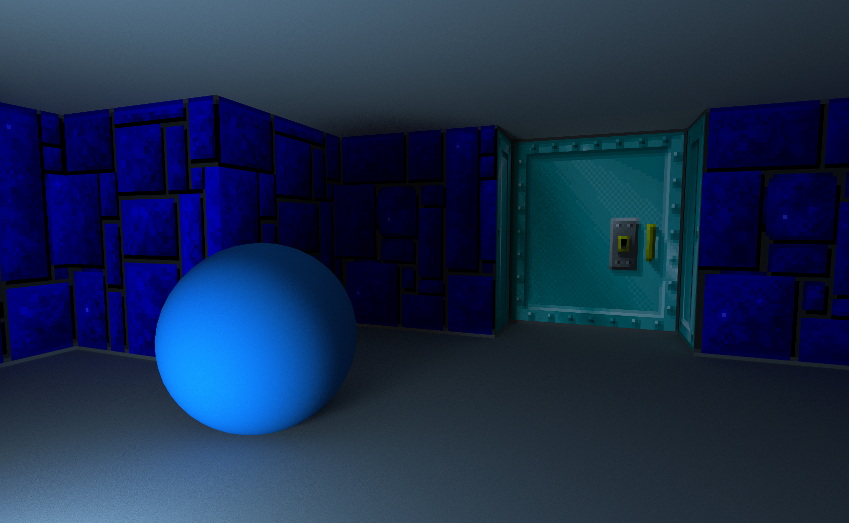
Noise Reduction
Even with the TAA enabled, there is still a lot of noise visible in this demo. The ceiling is especially hard to render because it is lit only by indirect lighting. The fact that the ceiling is a large, flat surface with a solid
I didn’t want to spend much time on this part of my demo, so I only tried one noise reduction filter: a Median3x3 filter by Morgan McGuire and Kyle Whitson. Unfortunately, this filter didn’t work well with the “pixel-art” graphics of the wall textures: it removed all detail in the distance and rounded the corners of nearby wall pixels.
In another experiment, I used the same filter on the Diffuse GI Render Target. Although this reduced the noise and kept the texture detail of the wall intact, I decided that the improvement was not good enough to justify the extra ms spent.
Demo
You can try out the demo here: https://renderqueue.dev/wolfenstein.