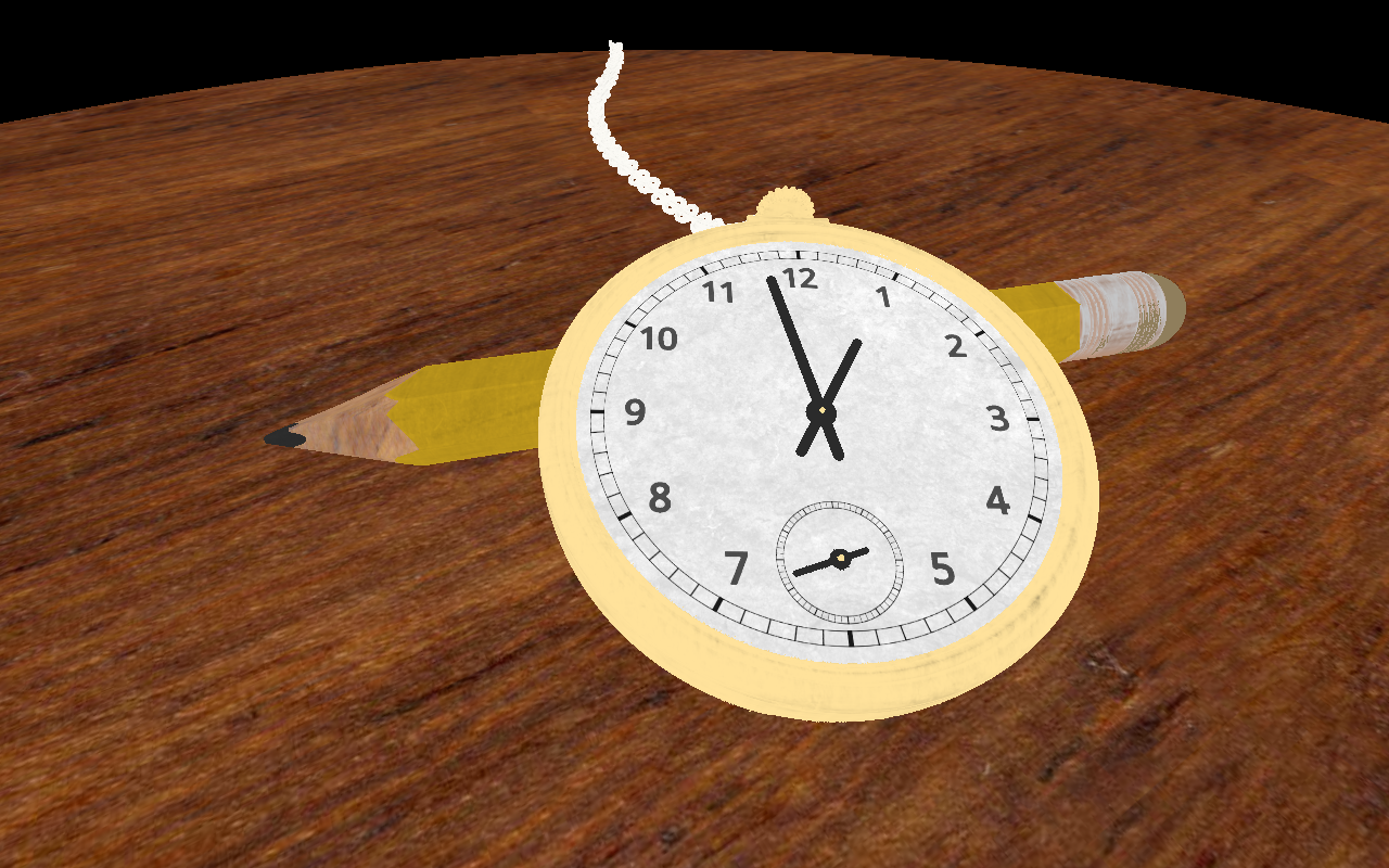
This shader uses Image-Based Lighting to render an old watch. The materials of the objects in the scene have physically-based properties.
The geometry of the old watch in the shader above is defined as a Signed Distance Field (SDF). For each fragment, a ray is constructed, and subsequently, the intersection point of this ray and the scene is found using raymarching.
To create a pretty image, each fragment (and thus each intersection point) should be shaded. If we try to simulate believable lighting, the shading of the surface at the intersection point normally depends on the following:
- The direction of the ray (the view direction of the observer).
- The material properties of the surface. For a material-specific BRDF, these properties define how light is reflected at the intersection point.
- The incoming light from every direction at the intersection point.
Physical-Based Materials
The materials are defined by physical-based properties: roughness, albedo, and “metallicness.”
Roughness is a value between zero and one; albedo is defined as an RGB colour, and metallicness is zero or one. Roughness, albedo, and metallicness are often used in Physical-Based Rendering (PBR).
Image-Based Lighting
In this shader, the incoming light is approximated by using a High Dynamic Range (HDR) cube map image of an environment, treating each cube map pixel as a light emitter. This technique is called Image-Based Lighting (IBL).
IBL is a technique that is already well-covered on the internet. In this post, I give a brief overview. Please look at the linked articles below if you are interested in (implementation) details.
I use the IBL implementation described in Real Shading in Unreal Engine 4 by Brian Karis of Epic Games. In this implementation, the lighting of a material is the sum of a diffuse and a specular component.
Diffuse
It is pretty straightforward to calculate the diffuse component. Because an ideal “matte” (Lambertian) surface is assumed for the diffuse lighting, the amount of reflected diffuse light at the intersection point does not depend on the view direction of the observer: it equals the cosine-weighted integral of the hemisphere centered around the normal N at the intersection point. Using the environment cube map as the light source, this integral can be pre-calculated and is stored in (a low mipmap of) a cube map.
In the lighting function of the IBL shader, the diffuse component is calculated by doing a lookup in the pre-calculated cube map using normal N. The final amount of diffuse lighting is weighted by a Fresnel coefficient and multiplied by the surface’s albedo. Note that metallic materials don’t have a diffuse lighting component (the weight is zero).
Specular-Split Sum Approximation
The specular component is harder to calculate because it depends not only on the view direction of the observer but also on the material’s roughness. Brian Karis of Epic Games proposes a Split Sum Approximation to solve the Rendering Equation of the specular component. This approximation gives two terms that can be separately pre-calculated:
- A first sum that approximates the unweighted amount of reflected incoming light at an intersection point is pre-calculated for different roughness values and stored in the mipmap levels of a cube map.
- A second sum gives weights for the reflected incoming light based on the roughness and
NdotV, i.e. the dot product of the normal and the view direction. Both the roughness andNdotVhave a value [0-1]. This makes it possible to pre-calculate and store the weights in a 2D texture.
In the lighting function of the IBL shader, the specular component is calculated by doing a lookup in the pre-calculated cube map using reflection direction R and a mipmap level based on the material’s roughness. The weight is found by doing a lookup in the pre-calculated 2D texture combined with a Fresnel coefficient.


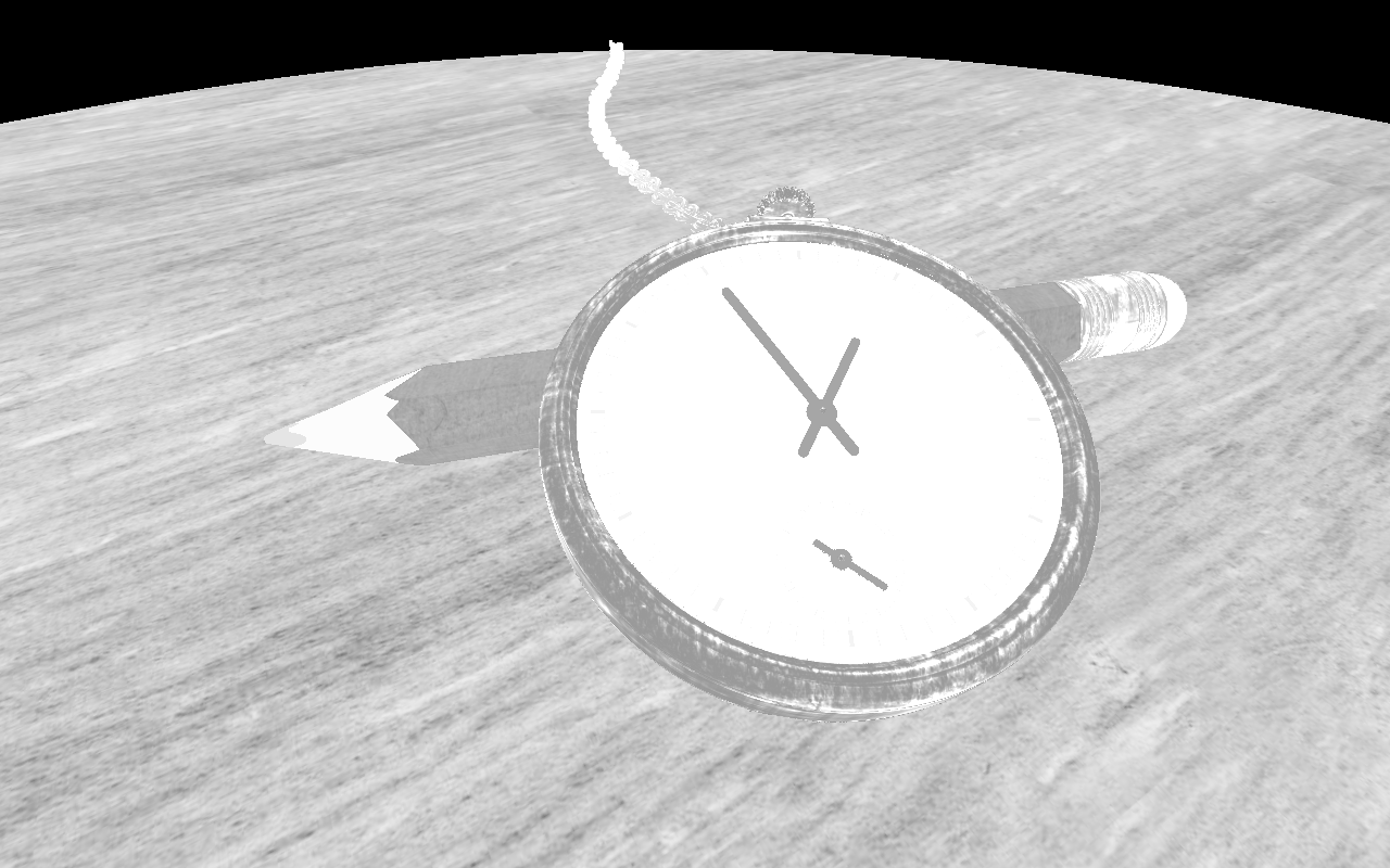
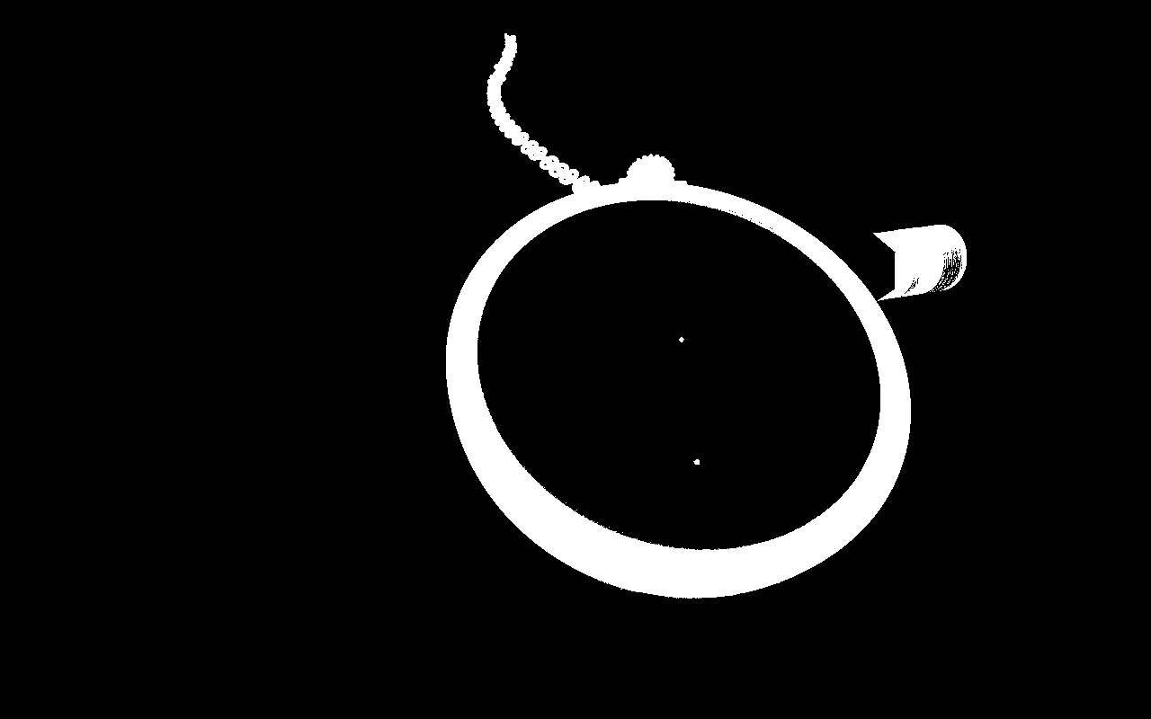
The images above show the different components of the lighting function of the IBL shader. Because an SDF is used to render the scene, it is easy (and cheap) to calculate an extra ambient occlusion term.
The final code of the lighting function in the IBL shader, with ro the ray origin, and pos the intersection point is given by:
vec3 lighting(in vec3 ro, in vec3 pos, in vec3 N, in vec3 albedo,
              in float ao, in float roughness, in float metallic ) {
    vec3 V = normalize(ro - pos);
    vec3 R = reflect(-V, N);
    float NdotV = max(0.0, dot(N, V));

    vec3 F0 = vec3(0.04);
    F0 = mix(F0, albedo, metallic);

    vec3 F = FresnelSchlickRoughness(NdotV, F0, roughness);

    vec3 kS = F;

    vec3 prefilteredColor = getSpecularLightColor(R, roughness);
    vec2 envBRDF = texture(iChannel3, vec2(NdotV, roughness)).rg;
    vec3 specular = prefilteredColor * (F * envBRDF.x + envBRDF.y);

    vec3 kD = vec3(1.0) - kS;

    kD *= 1.0 - metallic;

    vec3 irradiance = getDiffuseLightColor(N);

    vec3 diffuse  = albedo * irradiance;

    vec3 color = (kD * diffuse + specular) * ao;

    return color;
}Code language: GLSL (glsl)
Note that I do not pre-calculate the cube maps needed in the shader. Instead, I use (the mipmap levels of) a Shadertoy cube map that I have remapped using a random function to get something HDR-ish. This is incorrect and not how it is described in the article by Brian Karis, but I found the result for this scene good enough.
Full source code
You can find (the full source of) the fragment shader on Shadertoy: https://www.shadertoy.com/view/lscBW4.
Path tracing the same scene
I also created a shader that renders the same scene using a simple path tracer. You can compare the result here.
Further reading
- Real Shading in Unreal Engine 4 by Brian Karis of Epic Games.
- Implementation Notes: Runtime Environment Map Filtering for Image Based Lighting by Padraic Hennessy.
- https://learnopengl.com/PBR/IBL/Diffuse-irradiance by Joey de Vries.